Ready to control your lights from multiple locations? This guide provides a straightforward approach to understanding and implementing four-way switch wiring, ensuring a safe and effective installation. Let’s get started!
Four Way Switch Diagram: Mastering Multi-Location Lighting Control
Ready to control your lights from multiple spots in a room? Let’s tackle the seemingly complex four-way switch – it’s easier than you think! This guide will walk you through wiring a four-way switch setup, electrical safety, and practical insights, making those multi-location lighting dreams a reality.
Understanding the Basics of a 4-Way Switch
A 4-way switch, unlike a standard on/off switch, allows you to control a light from three or more locations. It achieves this by working in conjunction with two 3-way switches. Think of it as a middleman that alters the path of electricity depending on the position of all the switches in the circuit.
- 3-Way Switches: These are used at the beginning and end of the circuit and have three terminals (excluding the ground).
- 4-Way Switch: This goes in between the two 3-way switches and has four terminals (excluding the ground). Its internal mechanism changes the connections between the traveler wires, allowing the light to be turned on or off from any location.
Gathering Your Supplies: Everything You Need
Before you start, gather your tools and materials. Having everything ready prevents frustrating interruptions mid-project improving wiring connections. Here’s what you’ll need:
- Wiring: You’ll need the correct gauge wiring – typically 14-2 or 12-2 with ground, or 14-3 or 12-3 with ground, depending on your home’s existing wiring and local electrical codes. Check your local codes to ensure you are using the correct gauge for your circuit’s amperage.
- Switches: You’ll need two 3-way switches and at least one 4-way switch. If you need to control the light from more than 3 locations, you will need additional 4-way switches between the 3-way switches.
- Wire Strippers/Cutters: A sharp pair of wire strippers and cutters will make clean, precise cuts, crucial for secure connections for multi-location lighting. Klein Tools and Ideal are reputable brands known for their quality and durability.
- Wire Nuts: Use appropriately sized UL-listed wire nuts to create secure, insulated connections. 3M and Ideal are trusted brands.
- Electrical Tape: High-quality electrical tape, such as 3M Scotch 33+, is beneficial for insulating connections and providing an extra layer of protection.
- Voltage Tester (Non-Contact): A non-contact voltage tester like Fluke 1AC-A1-II is essential for verifying that the power is off before working on any electrical circuit.
- Screwdrivers: Have both Phillips and flathead screwdrivers with insulated handles on hand for switch installations.
- Pliers: (Optional) Needle-nose pliers can be helpful for manipulating wires in tight spaces.
- Work Gloves: (Optional) Insulated work gloves can provide an additional layer of safety.
Safety First: Electricity is Serious Business
This cannot be stressed enough: Always turn off the power at the breaker box before you start any electrical work. Identify the correct circuit breaker that controls the lighting circuit you’ll be working on. Flip the breaker to the “off” position. Don’t just rely on the light switch being off; use your voltage tester to double-check that the power is completely off at all wires and terminals at the wiring location. Test each wire individually. This single step prevents serious injury and potentially damaging house fires.
If you are not comfortable working with electricity, or if you are unsure about any step, it is best to consult a qualified and licensed electrician.
Understanding the Four-Way Switch: It’s Simpler Than It Sounds
A four-way switch isn’t some mysterious electrical wizardry – it’s a clever way to control a light from three or more places using traveler wires. Regular light switches are simple “on” or “off,” but a four-way switch system adds flexibility. This is achieved by using “traveler” wires, which act like messengers, carrying the electrical signal between multiple switches, creating a versatile lighting solution.
The magic happens in how these traveler wires are connected. They create a circuit that allows the four-way switch to act as a kind of go-between for your two three-way switches. The four terminals on a 4-way switch are arranged in pairs. Internally, the switch either connects one pair of terminals to the other directly, or it crosses them over. This simple action allows the circuit to be completed or broken from multiple locations.
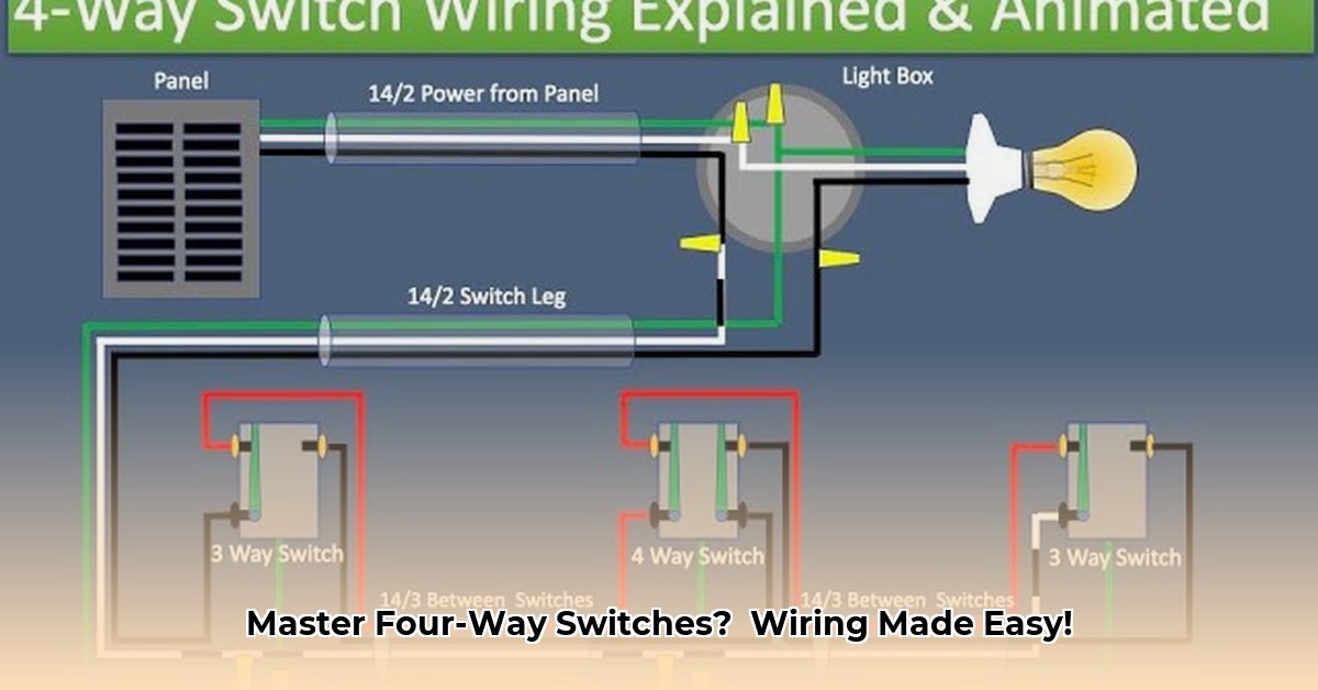
Wiring Diagrams: The Visual Guide to Success
Here’s where things get a bit more detailed, but don’t worry, it’s manageable. The arrangement of the “power in” and “load” wires on your three-way switches is important when mastering electrical wiring. If connected incorrectly, your system won’t work—and you’ll be left scratching your head!
(Insert clearly labeled and color-coded diagrams here. One diagram should show a power-in configuration where the power enters one of the three-way switches, and another diagram should show a power-out configuration, which is when the power source is positioned further away from the lighting fixture).
Let’s break down the key components you’ll see in your diagrams to enhance safety:
- Traveler Wires: These are the communication lines between switches and often are red and black, or other colors depending on the wiring scheme. These wires connect to the traveler terminals on the 3-way and 4-way switches.
- Power-In (Line) Wire: This is the “hot” wire, carrying power from your breaker box to the electrical system. In a typical 120V circuit, this wire is black.
- Load Wire: This wire goes directly to your light fixture ensuring electrical connectivity with lighting fixtures. It’s usually black and connects to the common terminal on one of the 3-way switches.
- Neutral Wire: This wire is essential for safety and proper operation of the circuit, crucial for proper electrical operation. Always connect it! In a typical 120V circuit, this wire is white. Neutral wires are usually connected together with a wire nut in each switch box, extending the neutral wire to the light fixture. Standard 3-way and 4-way switches do not connect to the neutral wire.
- Ground Wire: The ground wire connects to the ground and is for safety, providing a path for stray currents in your electrical setup. Always connect it! This wire is typically bare copper or green. The ground wire should be connected to the grounding screw (usually green) on each switch and light fixture box.
Step-by-Step Wiring Instructions: A Simple Approach
Let’s wire this thing! Here’s a clear, step-by-step process to guide you maintaining proper wiring safety:
- Switch Preparation: Carefully loosen the terminal screws on all your switches (3-way and 4-way). Strip about 1/2 inch of insulation from the end of each wire you’ll be connecting. Use wire strippers to avoid nicking the copper wire.
- Connecting the Three-Way Switches (Initial Connections):
- Identify the incoming power (hot) wire from the breaker box. This will connect to the “common” terminal on one of the 3-way switches. The common terminal is usually a different color (often black) than the other terminals.
- Connect the bare copper or green ground wire to the green grounding screw on the switch.
- Connect the white (neutral) wire. It will most likely be connected to other neutral wires in the electrical box with a wire nut. Do not connect the neutral wire to the switch.
- Connecting the Traveler Wires:
- Run a 3-wire cable (black, red, and white) between the first 3-way switch and the 4-way switch. Connect the black and red wires to the two traveler terminals on the 3-way switch (the terminals that are not the common terminal). Connect the other ends of these wires to one pair of terminals on the 4-way switch. It doesn’t matter which wire goes to which terminal in the pair.
- Run another 3-wire cable between the 4-way switch and the second 3-way switch. Connect the black and red wires from this cable to the other pair of terminals on the 4-way switch. Again, it doesn’t matter which wire goes to which terminal in the pair. Connect the other ends of these wires to the two traveler terminals on the second 3-way switch.
- Connecting the Load Wire:
- At the second 3-way switch, connect the “load” wire (the wire going to your light fixture) to the common terminal on the switch.
- Connect the ground wire to the green grounding screw on the switch.
- Connect the neutral wire. It will most likely be connected to other neutral wires in the electrical box with a wire nut. Do not connect the neutral wire to the switch.
- Connecting the Light Fixture:
- Connect the black wire from the cable coming from the second 3-

- Xbox Series S Crashing? Heres How to Fix It - March 30, 2026
- Xbox Crashing? Heres How to Fix Your Console - March 29, 2026
- Why Do My Xbox Games Keep Crashing? Unpacking the Reasons - March 28, 2026